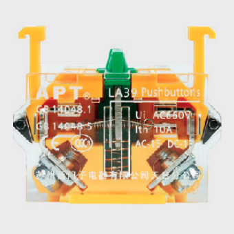
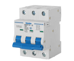
The push button switch is divided into start button (green button), stop button (red button) and compound push button switch (the color is not necessarily), and the different functions are determined by the position of the internal bridge-type moving contact. What is a bridge type moving contact?
Extended learning: What is the difference between NO and NC of the push button switches?
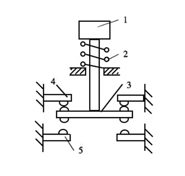
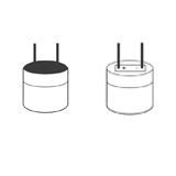
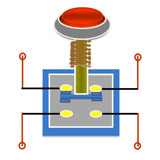
As shown in the above picture, 1 is the button cap, which is the color of green and red we mentioned above; 2 is the spring, which is the key to the use of the button switch with the contactor; 3 is the bridge-type moving contact; 4, 5 are static contact.
Everyone knows the characteristics of the spring (2). The biggest feature is that it will automatically reset when there is no external force. Therefore, when the button cap (1) is pressed, the spring (2) will be squeezed, causing the movable contact (3) to move down; when the button cap (1) is released, the spring (2) will automatically reset and drive the movable contact (3) Move up. Therefore, a start button and a stop button are formed.
Extended learning: What is the principle of the push button switches?
Start button
The start button has only one static contact (5). When the spring (2) is compressed, the moving contact (3) will contact the static contact (5) to form a closed circuit; after it is released, the spring (2) will automatically reset and move The contact (3) is disconnected from the static contact (5), forming an open circuit. The start button has two terminals on both sides of the static contact (5).
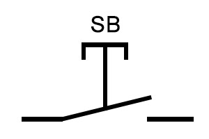
Therefore, the characteristics of the start button are produced: when the button is pressed, the circuit is energized, and when the button is released, the circuit is de energized. That is, when not operating, the button is in the normally open state. The graphic symbols of the start button in the circuit diagram are as follows:
Stop button
The stop button has only the static contact (4). When the spring (2) is compressed, the moving contact (3) will be separated from the static contact (4) to form an open circuit; after loosening, the spring (2) automatically resets, and the moving contact (3) contacts the static contact (4) to form a closed circuit. The stop button has two terminals on both sides of the static contact (4).
Extended learning: How does an emergency stop button work?
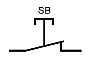
Therefore, the characteristics of the start button are produced: when the button is pressed, the circuit is de energized, and when the button is released, the circuit is energized. That is, when it is not in operation, the button is normally closed. The graphic symbols of the stop button in the circuit diagram are as follows:
Composite button
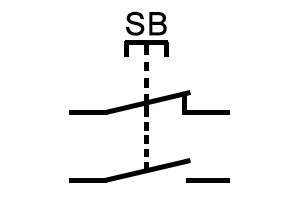
The compound button is the so-called mechanical interlock, which combines the stop button and the start button, so it is called "composite". The internal structure is exactly the same as the illustration, that is, the static contact (4) and the static contact (5) exist at the same time. Therefore, when the spring (2) is compressed, the movable contact (3) will be separated from the static contact (4) and contact the static contact (5) at the same time, so that the terminals at both ends of the static contact (4) will form an open circuit. Make the terminals at both ends of the static contact (5) form a closed circuit; the opposite is true after loosening.
This type of button has two terminals on both sides of the static contact (4) and the static contact (5), a total of 4 terminals. When connecting, 4 terminals can be connected to two circuits to make the two circuits form a mechanical interlock; you can also select the required two terminal connections from the 4 terminals to make it a start button or stop button.
The graphic symbols of the compound button in the circuit diagram are as follows:
Recommended article:
What is the principle of the push button switches?
What are the push button switches commonly used by electricians?
