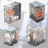
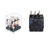
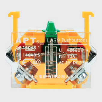
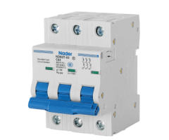
The working principle and characteristics of the relay
A relay is an electronic control device, which has a control system (also called an input loop) and a controlled system (also called an output loop), and is usually used in automatic control circuits. It is actually an "automatic switch" that uses a smaller current to control a larger current. Relay plays the role of automatic adjustment, safety protection, and conversion circuit in the circuit.
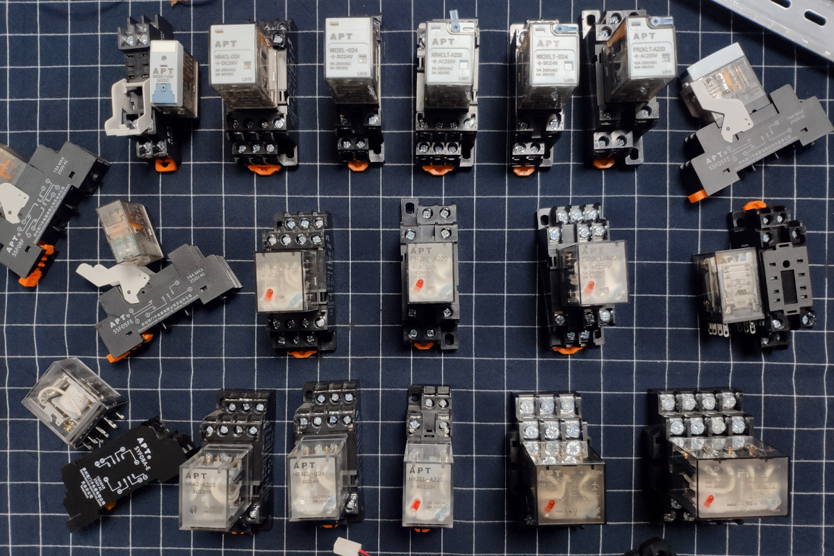
The working principle and characteristics of electromagnetic relay
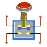
Electromagnetic relays are generally composed of iron core, coil, armature, contact reed, etc. When a certain voltage is added to the two ends of the coil, a certain current will be generated in the coil, which will produce electromagnetic effect. The armature will overcome the pulling force of the return spring to attract the iron core under the action of electromagnetic force, and the moving contact and the static contact (normally open contact) of the armature are closed. When the coil is de-energized, the electromagnetic attraction force disappears, and the armature returns to its original position by the reaction force of the spring, so that the moving contact and the original static contact (normally closed contact) are closed. In addition, the "normally open, normally closed" contacts of the relay can be distinguished as follows: the static contact that is in the off state when the relay coil is not energized is called "normally open contact(NO contact)"; the static contact that is in the on state The points are called "normally closed contact(NC contact)".
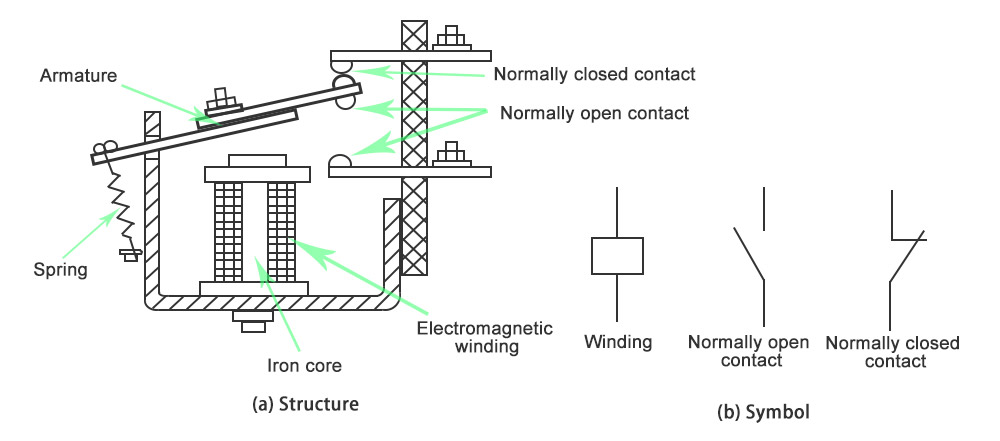
Structure and symbol of electromagnetic relay
The working principle and characteristics of thermal reed relay
The thermal reed relay is a new type of thermal switch that uses thermal magnetic materials to detect and control temperature. It consists of a temperature-sensitive magnetic ring, a constant magnetic ring, a dry reed tube, a thermally conductive mounting piece, a plastic substrate and some other accessories. The thermal reed relay does not use coil excitation, but the magnetic force generated by the constant magnetic ring drives the switch. Whether the constant magnetic ring can provide magnetic force to the dry reed tube is determined by the temperature control characteristics of the temperature-sensitive magnetic ring.
The working principle and characteristics of solid state relay (SSR)
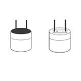
A solid state relay is a four-terminal device with two terminals as input and the other two terminals as output. An isolation device is used in the middle to achieve electrical isolation between input and output.
Solid state relays can be divided into AC type and DC type according to the type of load power supply. According to the switch type, it can be divided into normally open type and normally closed type. According to the isolation type, it can be divided into hybrid type, transformer isolation type and photoelectric isolation type, with the photoelectric isolation type being the most.
Main product technical parameters of relay
1.Rated working voltage
It refers to the voltage required by the coil when the relay is working normally. Depending on the model of the relay, it can be AC voltage or DC voltage.
2.DC resistance
It refers to the DC resistance of the coil in the relay, which can be measured by a universal meter.
3.Pull-in current
It refers to the minimum current that the relay can produce the pull-in action. In normal use, the given current must be slightly larger than the pull-in current, so that the relay can work stably. As for the working voltage applied to the coil, generally do not exceed 1.5 times the rated working voltage, otherwise it will generate a larger current and burn the coil.
4.Release current
It refers to the maximum current that the relay can release. When the current in the pull-in state of the relay is reduced to a certain extent, the relay will return to the unpowered release state. The current at this time is much smaller than the pull-in current.
5.Contact switch voltage and current
Refers to the voltage and current allowed by the relay. It determines the magnitude of the voltage and current that the relay can control, and this value cannot be exceeded during use, otherwise it is easy to damage the contacts of the relay.
Relay testing
1.Measuring contact resistance
Use the resistance profile of the universal meter to measure the resistance of the normally closed contact and the moving point. The resistance value should be 0, (In a more accurate measurement, the resistance is within 100 milliohms); and the normally open contact The resistance of the moving point is infinite. It can be distinguished which is a normally closed contact and which is a normally open contact.
2.Measure coil resistance
The resistance value of the relay coil can be measured with the universal meter R×10Ω to determine whether the coil has an open circuit.
3.Measure the pull-in voltage and current
Find an adjustable regulated power supply and an ammeter, input a set of voltage to the relay, and insert an ammeter in the power supply loop for monitoring. Slowly increase the power supply voltage. When you hear the pick-up sound of the relay, write down the pick-up voltage and current. For accuracy, you can try several times and find the average.
4.Measure the release voltage and release current
The connection test is also like the above. When the relay is closed, the power supply voltage is gradually reduced. When you hear the relay releasing sound again, write down the voltage and current at this time. You can also try several times to get an average release voltage and release current. Under normal circumstances, the release voltage of the relay is about 10-50% of the pull-in voltage. If the release voltage is too small (less than 1/10 of the pull-in voltage), it cannot be used normally, which will threaten the stability of the circuit, the work is unreliable.
The electrical symbol and contact form of the relay
The relay coil is represented by a long box symbol in the circuit. If the relay has two coils, draw two parallel long boxes. At the same time, mark the text symbol "J" of the relay in or beside the long box. There are two ways to represent the contacts of the relay: one is to draw them directly on the side of the long box, which is more intuitive. The other is to draw each contact into its own control circuit according to the needs of circuit connection. Usually the same text symbol is marked next to the contact and coil of the same relay, and the contact group is numbered. To show the difference.

Common symbols for electromagnetic relays
Selection of relay
1.First understand the necessary conditions:
The power supply voltage of the control circuit, the maximum current that can be provided;
Voltage and current in the controlled circuit;
How many sets and types of contacts are required for the controlled circuit. When selecting a relay, the power supply voltage of the general control circuit can be used as the basis for selection. The control circuit should be able to provide enough working current to the relay, otherwise the relay will be unstable when it is closed.
2.After consulting the relevant information to determine the conditions of use, you can search for the relevant information to find out the model and specification number of the required relay. If you have a relay in hand, you can check whether it can be used based on the data. Finally, consider whether the size is appropriate.
3.Pay attention to the volume of the appliance. If it is used for general electrical appliances, in addition to the cabinet volume, small relays mainly consider the circuit board installation layout. For small electrical appliances, such as toys and remote control devices, ultra-small relay products should be used.
4.In Quisure, you can select according to these parameters and quickly find the contactor products you need, which is simple and convenient.
Classification of relays
There are many classification methods for relays, which can be classified according to the principle of action, dimensions, protection characteristics, contact load, and product use.
Classification of relays according to the principle of action
1. Electromagnetic Relay
Under the action of the current in the input circuit, this kind of relay produces a predetermined response by the relative movement of the mechanical parts.
DC electromagnetic relay: An electromagnetic relay whose control current in the input circuit is DC.
AC electromagnetic relay: An electromagnetic relay whose control current in the input circuit is AC.
Magnetic latching relay: The magnetic steel is introduced into the magnetic circuit. After the relay coil is de-energized, the armature of the relay can still be maintained in the state when the coil is energized, with two stable states.
Polarized relay: A DC relay that changes state according to the polarity of the input excitation.
Reed relay: A relay that uses the action of a reed that is sealed in a tube and has the dual functions of contact reed and armature magnetic circuit to open, close or switch the circuit.
Energy-saving power relay: Electromagnetic relay whose control current in the input circuit is AC, it has the characteristics of large current (generally 30-100A), small size, and energy saving.
2. Solid State Relay
The relays without mechanical moving parts, the input and output functions are completed by electronic components.
3. Time Relay
When adding or deleting an input signal, the output part needs a delay or time limit before closing or disconnecting its controlled circuit.
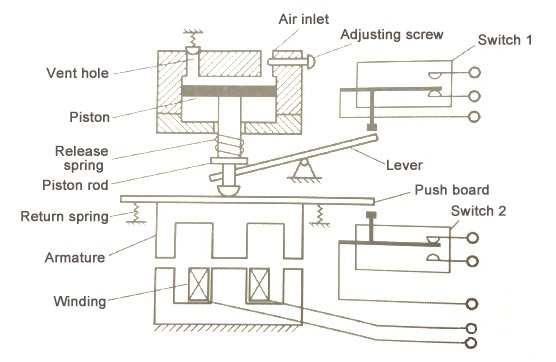
Structure of air damping time relay
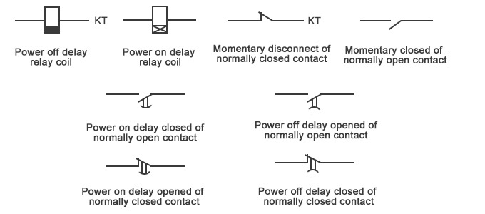
Common symbols of time relay
4. Temperature Relay
A relay that acts when the outside temperature reaches a specified value.
5. Wind speed relay
When the wind speed reaches a certain value, the controlled circuit will be turned on or off.
6. Acceleration Relay
When the acceleration of the moving object reaches the specified value, the controlled circuit will be turned on or off.
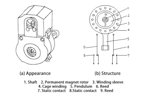
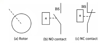
7. Other types of relays
Such as photorelay, acoustic relay, thermal relay, etc.
According to the size of the relay classification
Miniature relay: The longest side dimension is not more than 10mm relay.
Subminiature relay: a relay whose longest side dimension is greater than 10mm but not greater than 25mm.
Small relay: the longest side dimension is greater than 25mm, but not greater than 50mm.
Classification of relays according to contact load
Micro-power relay: a relay less than 0.2A.
Weak power relay: 0.2~2A relay.
Medium power relay: 2~10A relay.
High-power relays: relays above 10A.
Energy-saving power relay: 20A-100A relay.
Classification of relays according to protection characteristics
Sealed relay: The contact and coil are sealed in a metal cover by welding or other methods, and its leakage rate is low.
Plastic-encapsulated relay: A relay with a higher leakage rate by sealing the contacts and coils in a plastic cover using the method of sealing.
Dust-proof cover relay: a relay whose contacts and coils are enclosed by a cover to protect it.
Open relay: A relay that does not require a protective cover to protect contacts and coils.
Classification of relays according to usage
Communication relays (including high-frequency relays): The contact load of this type of relay ranges from low to medium current, and the environmental conditions are not high.
Machine tool relay: The relay used in the machine tool has large contact load power and long life.
Relays for household appliances: The relays used in household appliances require good safety performance.
Automotive relays: relays used in automobiles. This type of relay has high switching load power, high shock resistance and vibration resistance.
Small DC relay parameters
1. The DC resistance of the coil refers to the resistance value of the coil measured with a multimeter.
2. Rated working voltage or rated working current refers to the voltage or current value of the coil when the relay is working normally. Sometimes, only the rated operating voltage or rated operating current is given in the manual. At this time, you can use Ohm's law to calculate the rated current or rated voltage value that is not given: I=U/R, U=IxR, R is the DC of the relay coil resistance.
3. The pull-in voltage or current, which refers to the minimum voltage or current when the relay generates pull-in. If only the pull-in voltage is applied to the coil of the relay, the pull-in at this time is not reliable. Generally, the pull-in voltage is about 75% of the rated working voltage.
4. The release voltage or current refers to the voltage value when the relay changes from the pull-in state to the release state when the voltage across the relay decreases to a certain value. The release voltage is much smaller than the pull-in voltage. Generally, the release voltage is 1/4 of the pull-in voltage.
5. Contact load refers to the voltage and current value that the relay's contacts can withstand when switching.
