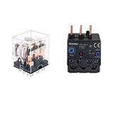
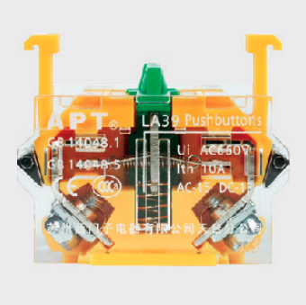
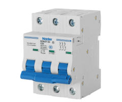
In order to select the relay correctly, it is necessary to understand the characteristics of the relay and confirm whether these characteristics meet the requirements of use. If it can be confirmed in the actual environment, it is more reliable.
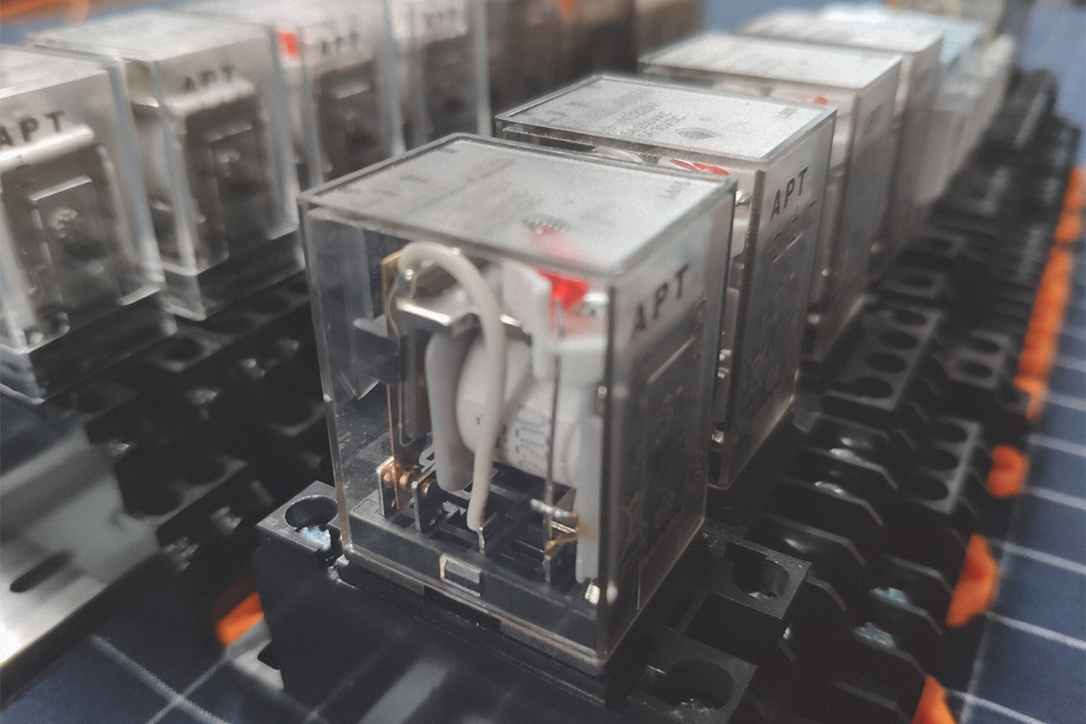
Refer to the following table for the selection principle of relays. After the items with "√" in the "must be determined" column are confirmed, a relay can be selected. If there are further requirements, the corresponding items with "√" in the "reference" column need to be further considered.
| Project | Need to consider | Must be determined | Reference | Influencing factors | |
| Contact | Contact load | AC, DC, size, type (inductive or resistive) | √ | Ambient temperature. For AC load, whether the action is synchronized with the load. Whether the contact material matches the contact. | |
| Contact form | NO, NC or conversion, several groups of contact pairs | √ | |||
| Electrical durability | Frequency of use, number of expected actions | √ | |||
| Contact material | What material | √ | |||
| Contact resistance | Size, test conditions | √ | |||
| Coil | Rated voltage | Size, direction, AC or DC | √ | Ambient temperature. Power fluctuations. The electric voltage drop when driving with a semiconductor. | |
| Coil resistance | Size, input power consumption | √ | |||
| Action voltage | Influence of size and power fluctuation | √ | |||
| Release voltage | Influence of size and power fluctuation | √ | |||
| Maximum allowable voltage | Size, time | √ | |||
| Coil temperature rise | What is the quantity, red insulation grade | √ | |||
| Performance | Packaging method | Open type, dust cover type, flux-proof type, plastic package type | √ | Environmental conditions. Security requirements. | |
| Dielectric Strength | Size, location | √ | |||
| Insulation resistance | Size, location | √ | |||
| Anti-vibration performance | Size, stability or strength | √ | |||
| Impact resistance | Size, stability or strength | √ | |||
| Use environment | Ambient temperature | High or low, time | √ | Insulation class. Packaging method. Service life. | |
| Atmosphere | Temperature, presence or absence of harmful gases | √ | |||
| Shape and installation | Shape | Shape size, shape height | √ | Installation size requirements. Installation method. | |
| Outlet form | PCB type, QC type, plug-in type, screw fixed type | √ | |||
| Welding method | Manual soldering, wave soldering, reflow soldering, etc., whether to clean | √ | |||
| Installation clearance | Gap, close | √ | |||
| Other | Safety certificate | UL、VDE、TUV、CQC | √ | Area. Customer request | |
| Special requirements and circumstances | Customer request | √ | |||
Contact
Contact load
When determining whether the load that the relay can withstand meets the requirements for use, in addition to determining the size of the load, but also to determine the type of actual load, because different loads have different steady-state values. Unless otherwise specified, the load given in the general specification is a resistive load.
The following table shows the relationship between typical load and impulse current and time.
| Type of load | Impulse current |
| Resistive load | 1 times the steady-state current |
| Motor load | 5-10 times of steady-state current |
| Capacitive load | 20-40 times of steady-state current |
| Transformer load | 5-15 times of steady-state current |
| Solenoid load | 10-20 times the steady-state current |
| Incandescent lamp load | 10-15 times of steady-state current |
| Mercury lamp load | 3 times the steady-state current |
| Sodium lamp load | 1 to 3 times the steady state current |
Contact material
For the same type of relay, different contact materials are applicable to different load types or ranges.
Remarks:
(1) Each relay must consider the maximum current value specified in the manual.
(2) When the general conditions permit, it is best to test and confirm in actual use.
(3) The gold-clad layer of the contact has better performance for medium and small loads. But for the load, it is usually only used to maintain the initial contact performance of the contacts before the relay is used.
| Material | Attributes | Typical application |
| AgNi + gold plated | The gold coating has better corrosion resistance in the air; Compared with other materials, it has smaller contact resistance and better consistency under small load; Good electrical conductivity and thermal conductivity; | Small load: there is almost no corrosion on the gold-plated layer, from 10mW (5V, 2mA) to 1.5W (24V, 62.5mA) (resistive load); Medium load: the gold coating is corroded after several actions, and AgNi basically plays the main role, from 2.4W (24V, 100mA) to 60W (30V, 2A) (resistive load); Note: When breaking a low load, the typical value is 1Mw (0.1V, 1mA) (for example, in a test instrument), it is recommended to use two pairs of parallel contacts. |
| AgPd | Good corrosion resistance and vulcanization resistance at room temperature; The contact resistance is small and the consistency is good; expensive; | Same as above |
| AgNi | Standard material for most relay contacts; Good electrical conductivity and thermal conductivity; High ablation resistance; Medium welding resistance; Easy to form vulcanized film in sulfide environment | Resistive load and small inductive load; Generally, the rated current is less than 12a; Generally, the surge current is less than 25A; |
| AgCdO | High AC load; Good electrical conductivity and thermal conductivity; High ablation resistance; Good adhesion resistance; It is easy to form vulcanized film in sulfide environment; | Resistive load, motor load and inductive load; Generally, the rated current is less than 30A; Generally, the surge current is less than 50A; |
| AgSnO2 | Excellent adhesion resistance; Material transfer is less than the above materials when DC loading; It is easy to form vulcanized film in sulfide environment; | Lamp load, inductive load and capacitive load; Very large surge current (up to 120A) load; |
| AgSnO2(Including other oxides) | Same as above | Lamp load, inductive load and capacitive load; Very large surge current (up to 120A) load; For different oxides, the applicable load will be different; |
Electrical durability
Unless otherwise specified, the electrical durability shown in the general manual is the nominal value measured under rated load, certain temperature, load ratio and operating frequency. Therefore, electrical durability will be different for other load types and switching frequencies. Generally, for loads above 2A, the electrical durability of the flux-proof and dust-proof type of the same relay is longer than that of the plastic-encapsulated type. Therefore, if the environment permits, try to use the solder-proof and dust-proof type of circuit breakers. Improve the service life of the relay.
Coil
Voltage
In order to make the relay work reliably, it is necessary to ensure that the working circuit can supply the rated voltage to the relay coil.
When a transistor is used to drive a relay, the voltage applied to the relay coil will be lower than the value of the drive circuit due to the inherent voltage drop of the transistor itself. It is recommended that the 4.5V specification relay is used when the transistor drive circuit voltage is 5V.
Sometimes in order to shorten the relay action time, the maximum allowable voltage can be applied to the coil in a short time, but the relay must not be overheated or even damaged. For polarized relays, please confirm the polarity of the coil voltage.
Coil resistance
In order to make the relay work reliably, it is necessary to ensure that the working circuit can supply the nominal coil power consumption to the relay, so the appropriate coil resistance must be selected.
Performance
Packaging method
In order to ensure the reliability of the relay, different packaging methods have different requirements for the post-processing of the relay.
Dielectric strength and insulation resistance
Please confirm that these two parameters can meet the requirements of use, and will not cause breakdown, short circuit, etc. of the line.
Anti-vibration performance and impact resistance
Please confirm that these two parameters can meet the requirements of use, and will not cause the relay to fail during use.
Use environment
Ambient temperature
Generally, the relay can work normally when the ambient temperature does not exceed the range specified in the manual.
Atmosphere
In high humidity, even condensation, and dusty environments, it is recommended to use plastic-encapsulated relays, because high humidity will accelerate the corrosion of the relay structural parts, and dust will easily cause the relay contacts to fail.
In environments containing silicone, it is recommended to use sealed products, because silicone will accelerate the failure of the relay contacts.
In environments containing H2S, SO2, NO2 and other harmful gases, the flux-proof type and dust cover type cannot be used, but the plastic package type can be used and tested and confirmed in actual use.
In actual use, if the ambient atmosphere is better, then it is recommended to use dust-proof or flux-proof relays, because the dust-proof or flux-proof relays can obtain longer electrical durability than the plastic package type.
Shape and installation
Shape and installation clearance
Generally, the external dimensions of relays have certain tolerances, so when designing the circuit and installation clearance, it is recommended to design according to the maximum size specified in the manual.
Welding method
The terminals of the relays are selected to be free of lead. The recommended soldering temperature and time are: 240℃~260℃, 2s-5s.
If reflow soldering is required, please confirm whether the instructions indicate that the relay can be reflow soldered.
Outlet form
The shape and installation method of the outlot can be selected according to the actual situation.
Safety certificate
Generally, UL/CUL certification is applicable to North America, and VDE and TüV certification are applicable to Europe. However, due to the international authority of these certifications, most other countries also recognize these certifications.
